

 |
50A Low Profile Mini Fuse
Product Details:
| Certification: | UL |
| Model Number: | 06D |
Payment & Shipping Terms:
| Minimum Order Quantity: | 5000PCS (1 Reel) |
|---|---|
| Price: | Negotiable |
| Packaging Details: | Tape in reel, 5000pcs per reel |
| Delivery Time: | 10-12 Days |
| Payment Terms: | T/T |
| Supply Ability: | 2KKPCS/Month |
|
Detail Information |
|||
| Type: | Surface Mount Fuse | Size: | 1608 |
|---|---|---|---|
| Current Range: | 250mA-5A | Voltage Rating: | 32VDC |
| Temp Range: | -55℃ ~+125℃ | Interrupting Rating:: | 35A(1.25A~5A)/50A(250mA~1A) |
| Testing Standard: | UL248-1 UL248-14 | Substrate: | Ceramic/glass Cover |
| Terminal: | Sliver Over-plated With Nickel And Tin | Element: | Sliver |
| Soldering: | Reflow Soldering: 260℃, 10s Max | Package: | Tape In Reel |
| High Light: | 50A Low Profile Mini Fuse,32VDC Low Profile Mini Fuse,50A surface mount thermal fuse |
||
Product Description
50A Low Profile Mini Fuse
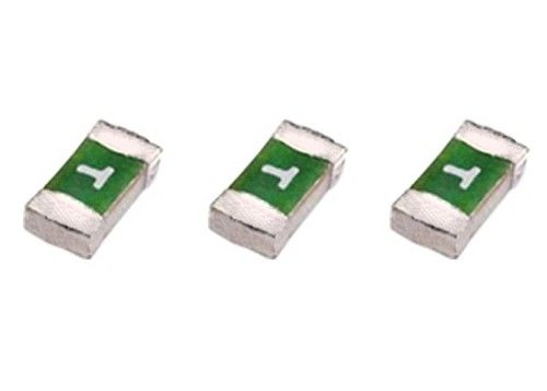
UL248-1 1608 Fast Acting Surface Mount Fuse 06D 250mA-5A 32V With Interrupting Rating 35A 50A
Description
1608 fast-acting Surface mount fuse are in small size can save space of PCB,suitable for lots of electronics board. , fuse is made of thin film, with low resistance, stable electrical properties and high reliability, and is adaptable to reflow and wave soldering, fuse has fast response and is suitable for the circuit without instantaneous current surge, fuse is mainly used in current protection, IC protection, mobile phone and other communication devices, display, digital camera, battery.
![]()
Dimension in mm
![]()
Specifications
| Catalog | Ampere | Voltage | Marking |
Melting Integral |
| No. | Rating | Rating | (A2.S) | |
| 06D0250D | 250mA | 32V | D | 0.00040 |
| 06D0375D | 375mA | 32V | E | 0.00087 |
| 06D0500D | 500mA | 32V | F | 0.00188 |
| 06D0750D | 750mA | 32V | G | 0.00880 |
| 06D1100D | 1A | 32V | H | 0.00250 |
| 06D1125D | 1.25A | 32V | J | 0.0125 |
| 06D1150D | 1.5A | 32V | K | 0.0310 |
| 06D1200D | 2A | 32V | N | 0.0480 |
| 06D1250D | 2.5A | 32V | O | 0.0615 |
| 06D1300D | 3A | 32V | P | 0.0690 |
| 06D1350D | 3.5A | 32V | R | 0.1181 |
| 06D1400D | 4A | 32V | S | 0.2380 |
| 06D1500D | 5A | 32V | T | 0.6817 |
Time-Current Features
| % of Ampere Rating | Opening Time | |||
| 100% | 4 hours Min | |||
| 200% | 60 s Max | |||
Others
| Blown Type | Fast-acting |
| Standard according to | UL248-1 UL248-14 |
| Interrupting Rating: | 50 Amperes at 32V DC(250mA~1A) 35 Amperes at 32V DC(1.25A~5A) |
| Operating Temperature | -55℃ ~+125℃ |
| Materials | Substrate:ceramic/glass cover Termination:sliver over-plated with nickel and tin Element:silver |
| Soldering method | Reflow soldering: 260℃, 10s max |
| Packaging | Automaton taped 5000PCS per rell, 150000PCS per carton |
| MOQ | 5000PCS |
| Lead time | 2 weeks |
| Agency | UL |
Application
White goods, power supply, industrial control,automotive,UPS,battery etc.
Features
Single blow fuse for overcurrent protection
1608 (EIA 0603) miniature footprint
Fast blow fuse
UL 248-14 listed
Surface mount packaging for automated assembly
Multilayer SMD design
RoHS compliant* and halogen free
Time-Current Characteristics Curve
![]()
Main Export Markets
Central/South America
Eastern Europe
Mid East/Africa
North America
Western Europe
Asia
Australasia
Selecting the right fuse
Choosing the right fuse can thwart equipment damage, prevent costly maintenance, and protect the user
The role of circuit protection devices has traditionally been labeled as perhaps the least important aspect of a design: an afterthought and an oftentimes irritating detail. Today, the sophistication of circuit design and the appropriate selection of a protective device require careful thought in the early stages and throughout.
It requires a competence, knowledge of varying types of devices, an understanding of the different functions they provide, and the ability to determine the most suitable device for an application. Choosing the right fuse ensures ongoing equipment function and prevents expensive maintenance due to nuisance blows. It protects the equipment altogether and, more important, the safety of the user.
Selecting the right fuse requires careful thought in the early stages of—as well as throughout—the design.
Circuit operating conditions
In order to begin selecting the appropriate fuse, one needs to understand the nature of the circuit it powers and protects. Basic operating factors such as the maximum steady-state voltage, current values, and ambient temperature have to be defined. Additionally, it is necessary to understand the peak value and duration/shape of surge currents that may exist.
Rated current and ambient temperature
Like most electrical components, fuses must be derated over temperature. At 60C, for example, a circuit that would use a 1-A time-delay fuse at room temperature will need a 1.25-A fuse to support operation at the higher temperature (see Fig. 1).
Fig. 1. The derating curve shown is a general curve for medium time-lag (T) and quick-acting (F). Refer to manufacturers product specific curves for each type of fuse.It is important to remember that the fuse has a resistance, and therefore will incur voltage drop and dissipate power. Time-lag fuses normally have lower voltage drops and power dissipation values than equally rated quick-acting fuses.
For example, a time-lag 2-A 5 x 20-mm fuse has a typical voltage drop of 60 mV, whereas the quick-acting version has a voltage drop of 90 mV. The reason for this is due to time-lag fuses having a thicker fuse wire diameter, which results in a higher I²t value or energy required to melt the fuse wire. Additionally, the fuse wire is tin-plated. This means that during normal operation, quick-acting fuses heat up to a higher temperature level before interrupting.
Fuse location
The location of the fuse in a circuit is also important to prevent unnecessary heat accumulation. The type and proximity of other components near and around the fuse affects ambient temperature.
Higher temperatures can effect the manufacturer’s specified time vs. current characteristics. Understand that measures taken to directly deflect heat away from the fuse—enlarged solder pads, cooling sinks, fans—are likely to change the stated performance characteristics.
Breaking capacity
Breaking Capacity is the maximum fault current in which the fuse can safely interrupt. Fuses used in situations where fault currents exceed the breaking capacity can catch fire or even explode in extreme cases.
For example, a fuse with a breaking capacity of 35 A should never be used when the power source exceeds 35 A worst case, but will offer adequate protection where fault currents do not exceed 35 A. Safety agencies determine acceptable breaking capacity limits according to predefined factors.
As a rule of thumb, a high-breaking-capacity fuse is recommended for circuits with inductive load, a p.f. of less than 0.9. A low-breaking-capacity fuse is usually sufficient for circuits with resistive/capacitive loads.
The actual power factor of the equipment can affect the manufacturer’s specified ratings. Some manufacturers provide additional breaking capacity ratings at varying power factors to further assist customers in determining suitability of a product.
Time-current characteristics
Some applications have specific and easily understood needs when it comes to the speed at which the fuse should blow. Sensitive semiconductor circuits oftentimes need fast-acting fuses that blow within very short periods of time, while equipment taking large inrush currents may need a time-lag fuse to prevent nuisance outages.
In cases where either type could be used, it is helpful to refer back to the effect of ambient temperature in making the selection and remember that time-lag fuses typically have a lower voltage drop than fast-acting fuses and therefore dissipate less power. Pre-arcing times at moderate overcurrents (1 < 2.5*In) are almost the same (see Fig. 2). At greater overcurrents (1 = 10.0*In), time-lag fuses have higher prearcing times than quick-acting fuses.
Fig. 2. Pre-arcing times for quick-acting and time-lag fuses at moderate overcurrents are almost the same.
Calculating melting energy
I2t is a measure of the energy required to melt the fuse wire in the fuse. The approximate length of time it will take for a fuse to blow can be determined by dividing the I2t value specified by the manufacturer by the square of the expected fault current.
For example, for a fuse with I2t = 4.5 A2s the expected fault current is 13 A:
ttyp = I2t/I2 = 4.5 A2s/(1.25 A * 10)2 = 28.8ms
Conversely, knowing the expected fault current value and having in mind a specific time one wants a fuse to blow in, it can be determined what I2t value is needed for a specific requirement. Once the required I2t has been determined, it is relatively easy to check a candidate fuses’ specification to find the fuse that meets one’s needs.
Available product types
The IEC standards cover miniature fuses for equipment in a large number of different sizes and package types, ranging from 5x20-mm cartridge types to 1206 SMD. Terminal variations include pig-tails, through-hole, and SMD, and are offered in bulk or tape and reel, typically the case for chip fuses.
There are some unique differences between the IEC standards versus the UL standards, and compliance with one or the other or both must be considered when looking at domestic and export markets. It is not necessarily possible to substitute a UL fuse with an IEC or vice-versa, although one might think that one 1-A fuse is just like another. Time-current characteristics are different, and where a UL fuse may blow in a matter of hours when operated at 1 A, a fuse designed to IEC should not blow at all at 1 A, and may suggest that a 2-A fuse is needed.
Making the final selection
Once the rated voltage and currents, breaking capacity, and time-current characteristics are determined together with the current I2t, and the desired package styles are known, it is possible to check candidate types for a fit. If the fuse is to be mounted in a fuseholder, it is especially important to observe power dissipation limits of the both the fuseholder and the fuse.
The appropriate fuseholder
Fuses are often mounted in holders to facilitate ease of replacement. The fuseholder will have additional important electrical characteristics: contact resistance and maximum allowable fuse power dissipation.
One must also keep in mind that the holder, like the fuse, must also be derated at higher temperatures. Fuseholders are available in many styles for panel mounting in equipment where fuses need to be user replaceable, and as clips or blocks that can be mounted to the chassis or PCB inside the equipment.
Both types can be found with quick-connect terminals or PCB terminals, and PCB types are available for through-hole or SMD connections. PCB holder types are available for vertical or horizontal mounting to allow flexibility in chassis design. Some types are even available with fuses already installed for faster assembly and lower installed cost.